Real-Time Vision Analysis for Painting Strokes
Applying Computer Vision Techniques to Robotic Painting
1.Summary
The objective of this mini project was to explore a practical solution for implementing a feedback system for a robotic painter. This work was initially intended to be part of my PhD research under the CoRoM scholarship in collaboration with Acrylic Robotics. However, I was only able to dedicate a limited amount of time to it. The results presented here are shared for technical insight purposes, as the system was never tested on a real robotic painter and remains an incomplete exploratory study.
As discussed in Link, one of the main challenges in robotic painting is limited precision, which led me to believe that an external control loop was necessary to manage brush–canvas interaction more effectively. Several potential approaches can be considered, but any viable solution must operate in real time, remain cost-effective, provide sufficient accuracy, and avoid imposing constraints on the robot’s motion.
I explored the possibility of combining computer vision with a laser-based distance sensor. A camera-based system can provide detailed spatial information, while laser-based sensors can offer robustness under varying environmental conditions. The goal was to investigate whether integrating these modalities could enable more reliable brush–canvas interaction control. In the following sections, I present the hardware setup and some initial computer vision results from this exploratory study.
2.Technical Stack
🔧 Key Software & Frameworks:
- OpenCV (real-time image & video processing)
- Segment Anything Model (SAM)
- SparkFun VL53L4CD ToF distance sensor
- Arduino / SparkFun RedBoard platform
- HAAR Cascade training tools (OpenCV)
🧠 Methods & Algorithms:
- Real-time vision-based measurement pipeline
- Color detection & contour extraction
- Edge detection (Canny)
- Image thresholding techniques
- HAAR cascade object detection
- Pixel-to-metric calibration & geometric measurement
- Sensor calibration & offset correction
- Sensor–vision fusion concepts
💻 Languages:
- Python
- C++
3.Time-of-Flight (ToF) sensor
Since I required an affordable range-finder sensor, I selected the SparkFun Distance Sensor VL53L4CD, which offers a good balance between cost and accuracy. The sensor can be purchased directly from the SparkFun website. A SparkFun RedBoard Plus, which is similar to an Arduino Uno, was used to control the sensor.
To evaluate the sensor’s range and accuracy, I built the simple experimental setup shown below.

3.1.Sensor offset calibration
To calibrate the sensor, the Example7_Calibration code should be executed. The original SparkFun calibration example did not work correctly in my case. I added distanceSensor.startRanging(); at line 86, which resolved the issue.
For accurate calibration, the official documentation recommends using a light gray (17% gray) target. However, I performed calibration using white paper.
After uploading the code to the board:
- Place the target in front of the sensor at a distance below 10 cm.
- When the sensor detects the target at this distance for at least 1 second, a 5-second buffer begins.
- During this buffer period, move the target to a distance of 140 mm from the sensor.
The offset value corresponds to the difference between the real distance and the measured distance. The sensor automatically stores this value in memory. Additionally, I included the setOffset() function after begin() in my code to ensure that the calibrated offset is applied properly.
In my case, the offset was approximately: Real Distance – Measured Distance = 20.37 mm
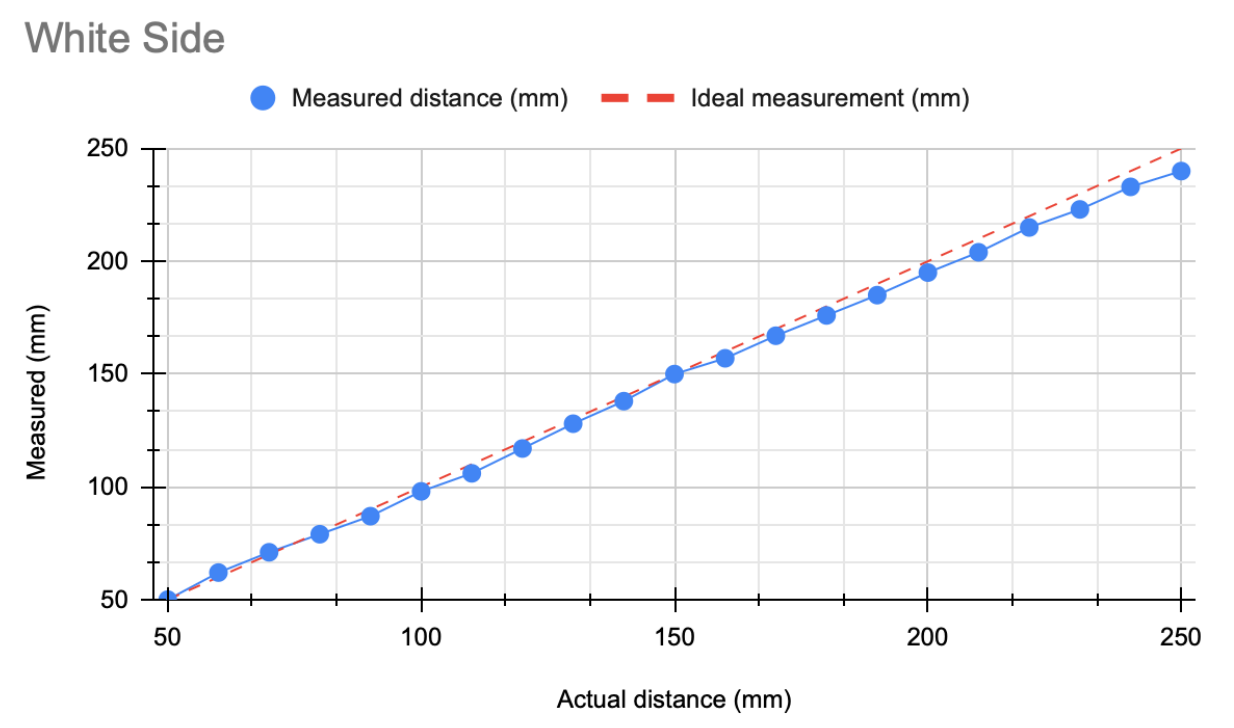
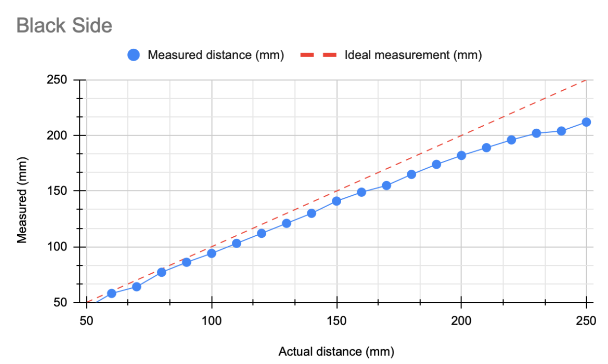
3.2.Accuracy measurement
Test 1: 1–20 cm Range
In the first experiment, I evaluated distances between 1 cm and 20 cm. Measurements were taken every 1 cm, with sampling performed every 4 seconds. To improve reliability, I sampled at least twice per distance.
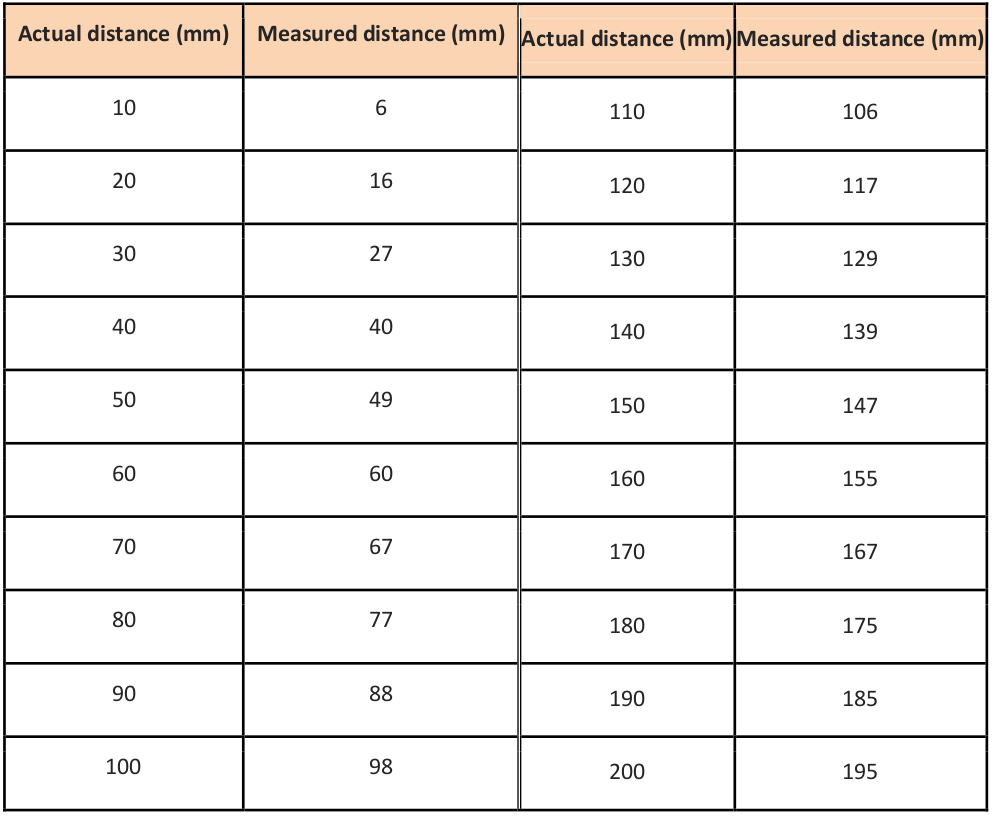
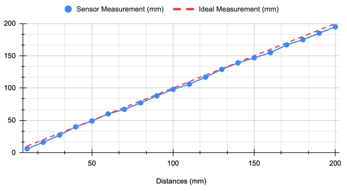
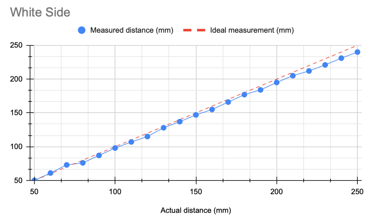
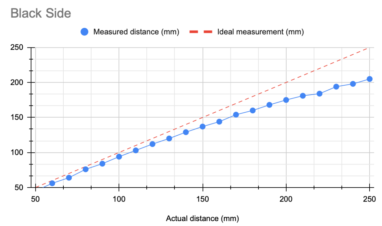
Test 2: 20–50 cm Range
The second experiment covered a range of 20 cm to 50 cm using the same sampling approach.

Note: Measurement variation ranged from approximately ±1 mm (minimum) to ±7 mm (maximum). The reported values are based on three to four measurements per distance, selecting the most consistent results.

Test 3: Fine Resolution (20–25 cm, 2 mm Steps)
In this experiment, I focused on a narrower range (20 cm to 25 cm) with sampling every 2 mm.

The accuracy was not satisfactory, and there was no consistent linear relationship between small distance changes and sensor output.

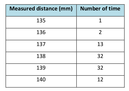
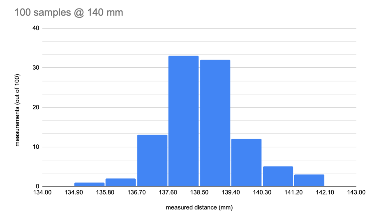
To evaluate measurement stability, I collected 100 samples at the calibration distance (14 cm). The histogram below illustrates the distribution of readings.
Minimum measured distance: 135 mm
Maximum measured distance: 142 mm
3.3.Sampling Rate
- Approximately 86 samples per 5 seconds
- Average sampling interval: 0.058 seconds
- Approximate frequency: 17.2 Hz
Depending on the distance, the signal rate varied between approximately 10 Hz and 18 Hz.
3.4.Effective Range
Based on the measurements, the effective operating range of this ToF sensor appears to be between 5 cm and 15 cm. These values were obtained under normal lighting conditions and using wood or paper materials. Performance may vary under different environmental conditions.
3.5.Effect of Surface Color on Measurements
Surface reflectivity in the infrared (IR) spectrum significantly influences sensor performance.
- White Surfaces
- High IR reflectivity
- Strong return signal
- More accurate distance measurements
- Black Surfaces
- Low IR reflectivity
- Weaker return signal
- Reduced measurement accuracy
The following results are based on single calibration:
I then recalibrated separately for each color.
-
Lighter colors provide more accurate measurements.
-
Separate calibration for each color does not significantly improve accuracy.
-
In some cases, recalibration for black surfaces produced slightly worse results (possibly due to measurement noise).
3.6.Effect of Material on Measurement
- Wood
- Reflectivity varies depending on type and finish.
- Many wood types exhibit moderate to high IR reflectivity.
- Generally provides reliable distance readings.
- Paper
- Often highly reflective in the IR spectrum.
- White paper produces strong return signals and accurate measurements.
- Darker or colored paper reduces reflectivity.
- Cotton
- Reflectivity depends on color, weave, and texture.
- Light-colored cotton performs reasonably well.
- Dark or highly textured fabrics reduce signal strength.
3.7.Overall Conclusion
-
The sensor does not provide fully stable measurements; tolerance ranges from ±1 mm to ±7 mm.
-
It performs best within a close-range window of 5–15 cm.
-
Darker surfaces reduce measurement accuracy.
-
Sensor angle influences measurement reliability.
-
Although material properties affect readings, recalibration can partially compensate for these effects.
3.8.GitHub code
The PDF explanation and codes are available here: Link
4.Vision Detection
In addition to sensor-based feedback systems, I believe real-time computer vision methods can be explored to analyze stroke thickness and length during painting. One possible approach is to convert the video stream into individual frames at fixed time intervals (every X seconds) and then apply image processing techniques to each frame. The general procedure is illustrated in the flowchart below:

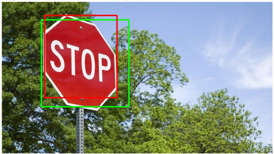
To explore a vision-based feedback approach, I developed a pipeline that integrates video processing, object detection, color detection, and geometric measurement. First, the video stream is converted into images every three seconds using a built-in camera and the OpenCV library. For object detection, I initially trained and tested the system using a Stop Sign dataset; however, the framework is flexible and can be adapted to any custom dataset. In this specific case, color detection was focused on the red channel to isolate painted regions. To improve robustness, I combined both object detection and color detection by comparing their extracted contours. A simple overlap ratio (ranging from 0 to 1) was computed to evaluate how much the contours intersected, and a threshold of 0.7 was used to select only the common areas. This allowed the system to filter unreliable detections and retain consistent regions from both methods.

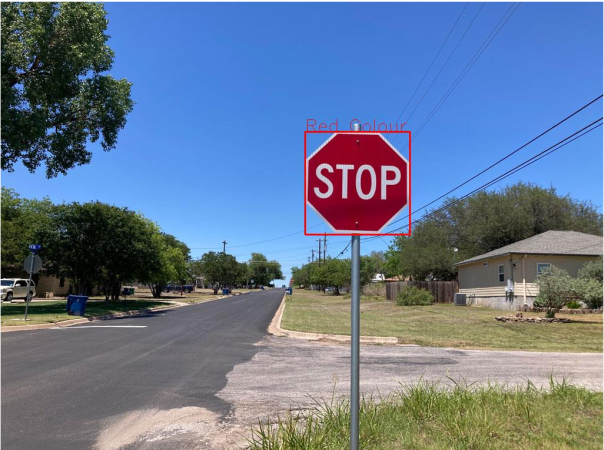
To enable real-world measurement, a reference object of known length (e.g., a 15 cm notebook) was used to calculate the pixel-per-metric ratio using the formula pixels_per_metric = object_width / known_width. Once calibrated, this ratio allows other object dimensions to be estimated accurately. However, several practical constraints must be considered: the camera angle should ideally be 90 degrees for accurate measurement, lighting variations affect color detection reliability, and objects with significant tilt may not always be detected correctly. After integrating color detection, object detection, and measurement into a unified pipeline, I evaluated the combined system across various images (red box: color detection; green box: object detection; blue box: measurement). For reliable operation, a calibration step is required beforehand. A fixed reference image is used to define expected color, shape, and size features, and the resulting pixel-per-metric value can then be applied to subsequent images under similar conditions.
1- Creating a Custom HAAR Dataset
As an initial experiment, I created a HAAR cascade dataset for iPhone detection (as an example use case). The dataset consisted of one positive image and 50 negative images. The detection performance was not satisfactory, and some example results are shown below.

2- Modifying Training Parameters
To improve detection accuracy, I retrained the HAAR model using more negative images and increased the number of training stages. I also adjusted parameters such as maxFalseAlarmRate to improve performance. Although the results improved for iPhone detection, the method clearly requires a significantly larger dataset and longer training time to achieve reliable accuracy.
Conclusion: I do not believe that object detection at this early stage is sufficiently robust for the intended application, especially when the detectable item is small and the camera resolution is limited. In addition, light reflections have a significant impact on detection reliability.
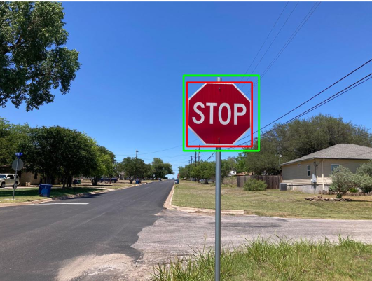
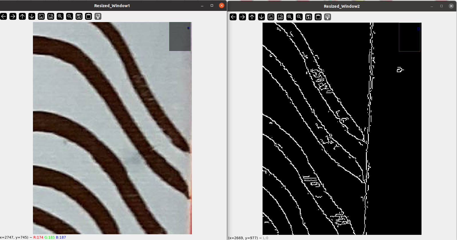
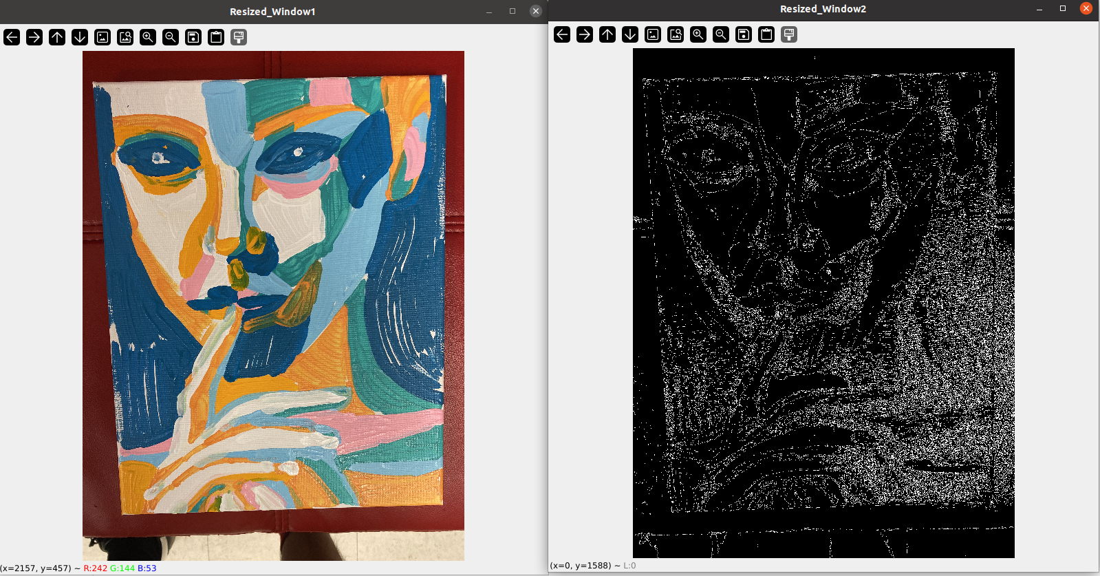
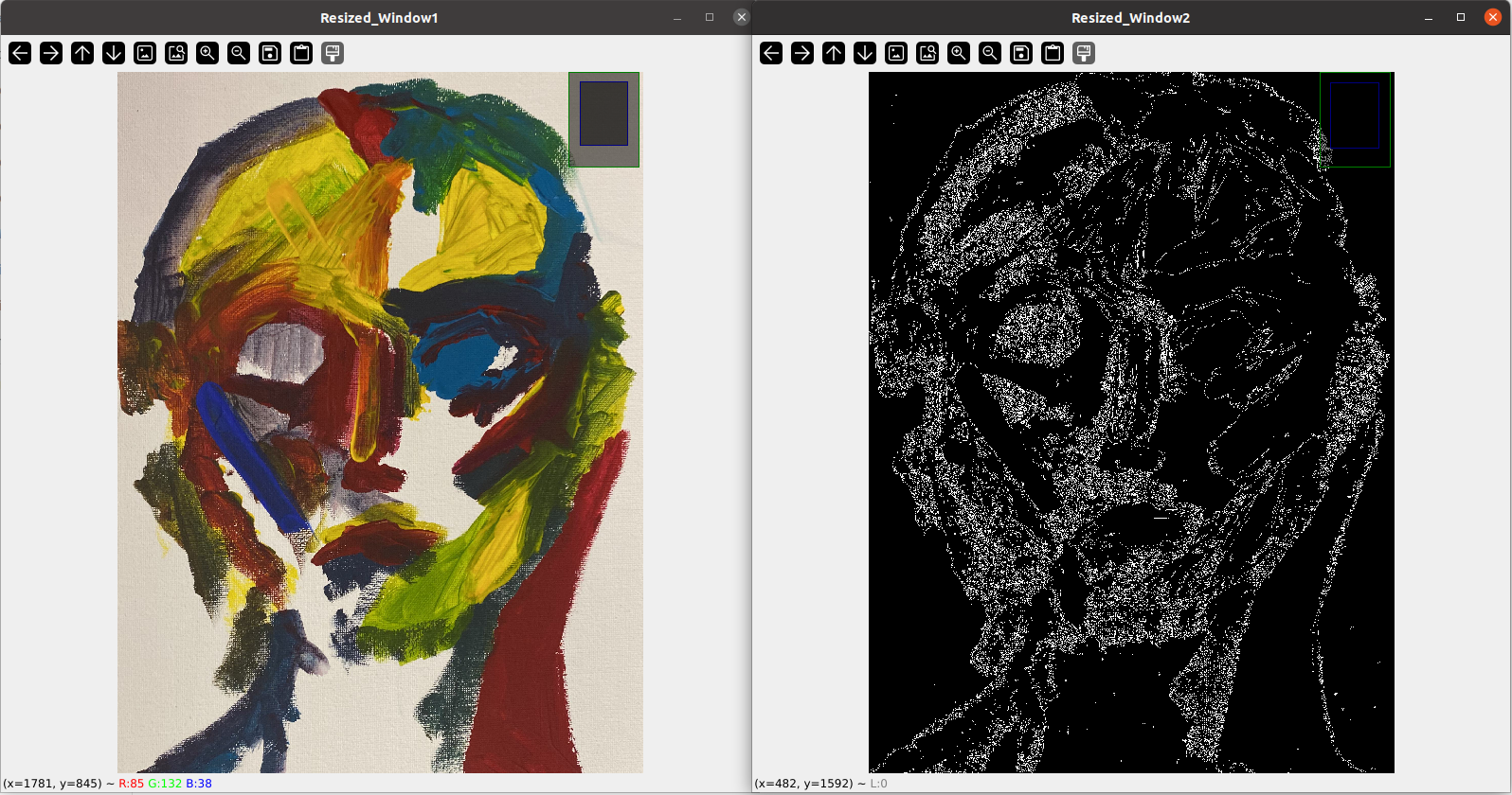
3- Canny Edge Detection
Instead of relying solely on color or object detection, I explored edge detection techniques to extract brush features for rough measurement. I first applied Canny edge detection using OpenCV on several painted samples.
The results were not highly accurate and were heavily dependent on lighting conditions. Moreover, Canny detected not only stroke edges but also many irrelevant edges from the background and other elements in the scene.
I also experimented with the L2gradient option, but the improvements were minimal.
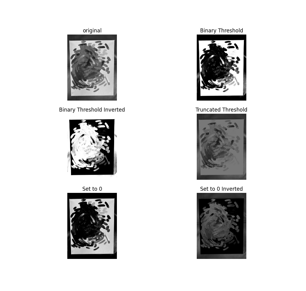
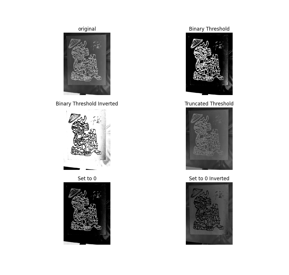
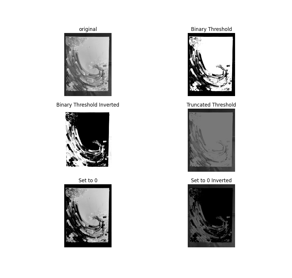
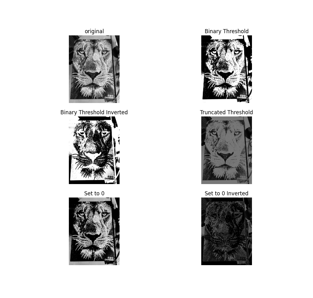
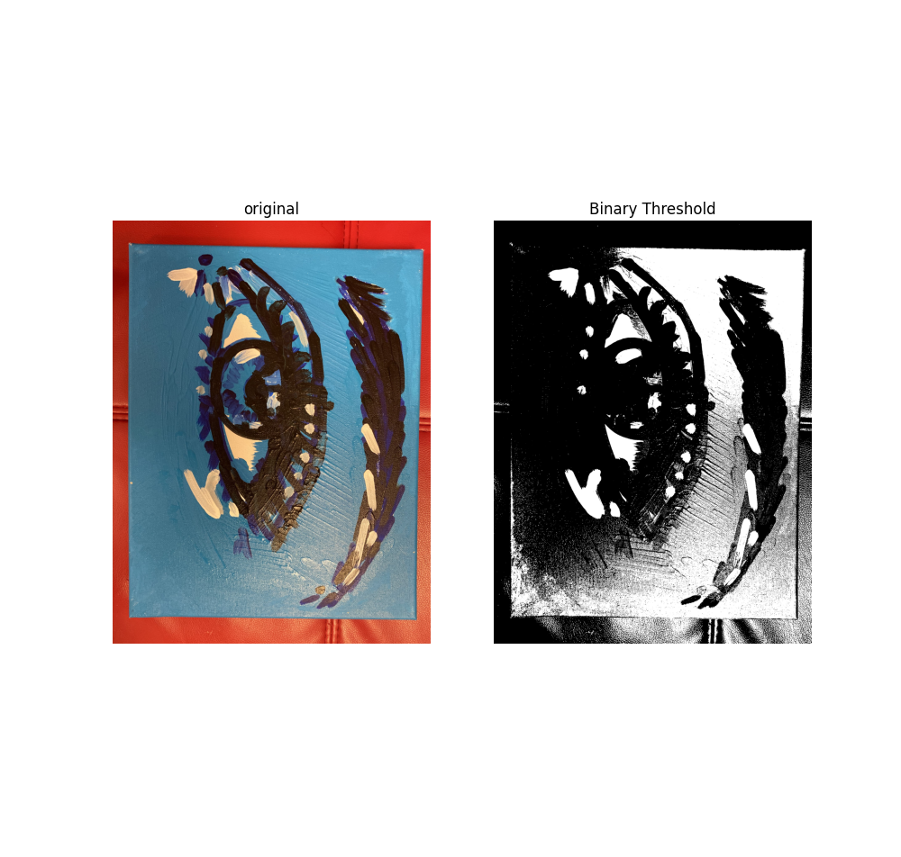
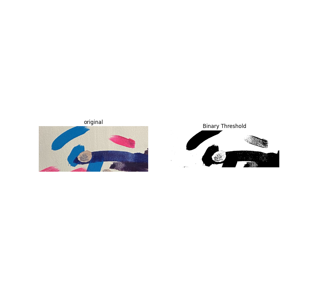
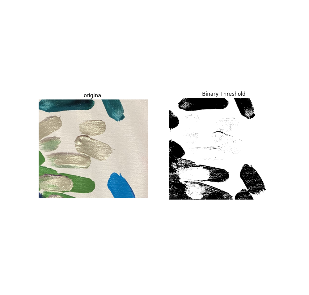
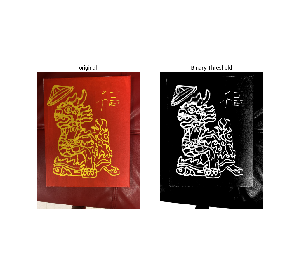
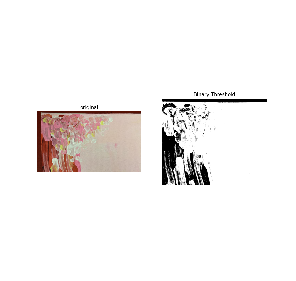
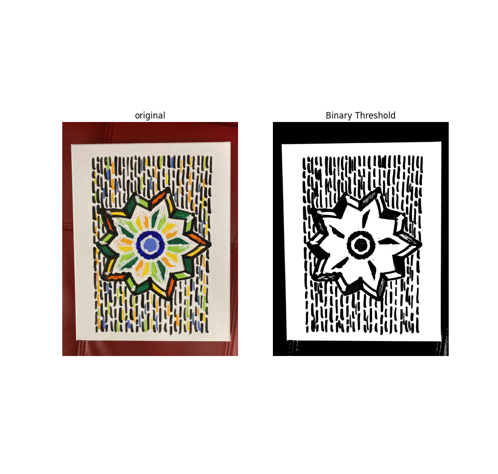
4- Thresholding Methods
I tested several thresholding techniques, including:
- Binary Threshold
- Binary Threshold Inverted
- Truncated Threshold
- Set to 0
- Set to 0 Inverted
These methods were evaluated for their ability to isolate stroke features.
Overall, the results were moderate. However, thresholding performance degrades significantly when lighting conditions are uneven or when the stroke color is light. Sample results for different thresholding approaches are shown below.
5- Segment Anything Model (SAM)
Finally, I tested the Segment Anything Model (SAM) demo as a potential future solution. The processing speed was satisfactory, and the segmentation accuracy was impressive.
However, the method requires providing prompts or guidance about the desired segment. For fully autonomous stroke detection, additional integration or customization would be necessary.

5.Project Recap
This research project focuses on measuring the real-time distance between a collaborative robot’s gripper and an object, such as a white painting canvas. The application requires high precision (less than 0.5 mm error), low cost, real-time performance without noticeable delay, and consistent functionality.
The ultimate objective is robotic painting. To produce high-quality strokes, the robot must maintain a fixed and controlled distance from the canvas at all times. Even small deviations in distance can significantly affect stroke thickness and painting consistency. Therefore, precise and stable distance control is essential.
5.1.Stage 1: Time-of-Flight (ToF) Sensor
In the first stage, I tested a ToF range finder. While it performed reasonably well, it consistently exhibited a measurement tolerance of at least 1–2 mm. Given the sub-millimeter accuracy requirement, this level of tolerance is insufficient.
As a result, relying solely on ToF measurements is not adequate. Either a more precise sensor is required, or sensor fusion techniques must be explored to improve overall accuracy.
5.2.Stage 2: Computer Vision Approach
In the second stage, I explored the possibility of integrating fast computer vision algorithms using OpenCV. I implemented a combined pipeline consisting of object detection, color detection, and measurement estimation. The system initially relied on the HAAR Cascade detection algorithm, and results for standard input images were promising.
I then created a custom dataset tailored to the painting application. However, brush stroke detection using computer vision proved to be insufficiently accurate. I developed and trained my own HAAR dataset, but the results remained unreliable.
I also experimented with edge detection methods to extract brush stroke shapes and features. These techniques were highly sensitive to lighting conditions and color variations, making them inconsistent for practical use.
5.3.Final Reflection: Two Feedback System Strategies
From these experiments, two potential feedback system strategies emerge:
1- Post-Processing with a Fixed High-Resolution Camera
This approach involves analyzing images after each stroke using a fixed high-resolution camera. It works well when the stroke thickness is less than desired and can still be corrected (e.g., increased). This strategy can be integrated with additional image processing pipelines to evaluate color consistency, stroke thickness, and coverage. However, it is inherently corrective rather than preventative.
2- Real-Time Distance Measurement Before Each Stroke
The second concept focuses on maintaining a fixed distance before and during each stroke using real-time measurement. This strategy is more general and can address both under-thickness and over-thickness cases. However, it requires highly accurate and fast sensors capable of operating at high frequencies. The primary challenge is finding sensors that are both precise and affordable. Based on my tests, a ToF sensor alone is insufficient and would require either higher-grade hardware or integration with complementary sensing methods to achieve the desired accuracy.